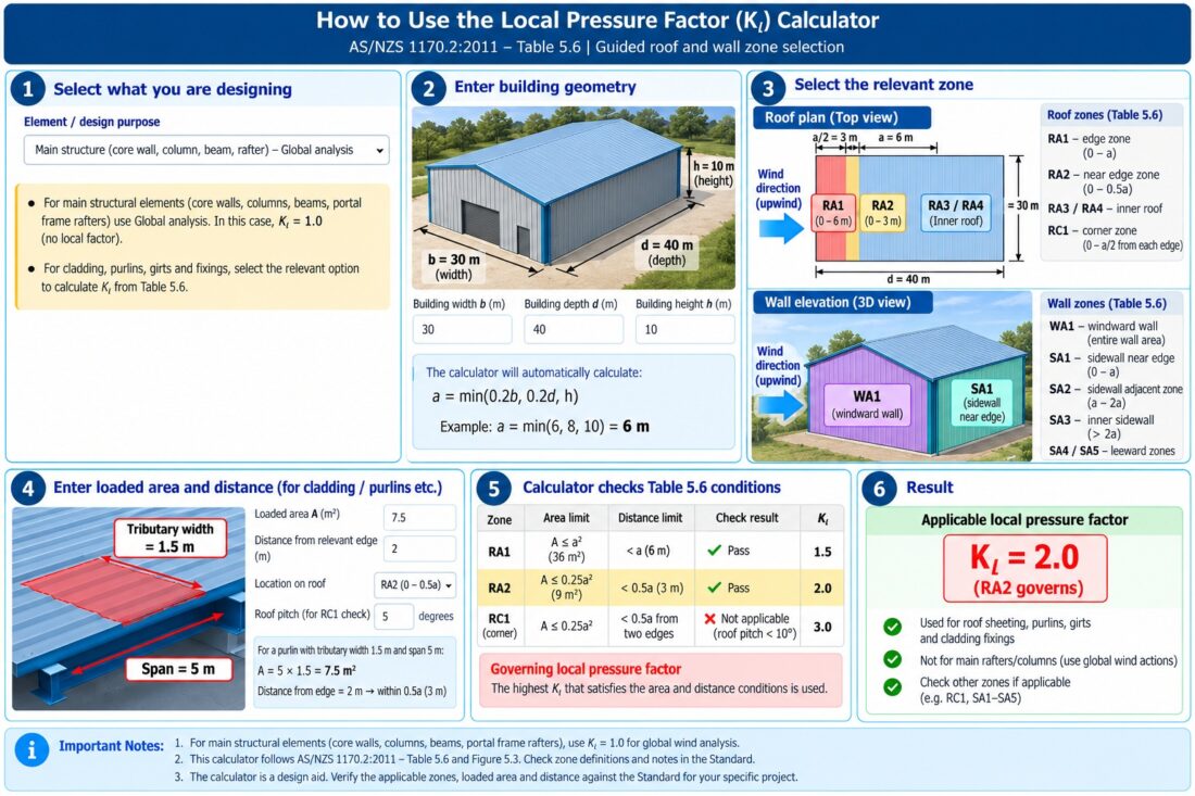
Local Pressure Factor (Kl) Calculator
AS/NZS 1170.2:2011 — Table 5.6 | Guided roof and wall zone selection
1. What are you designing?
2. Building geometry and loaded area
3. Factor to use for the selected element
Use this value for overall wind analysis of core walls, columns, primary beams and main portal frame rafters. This is not a cladding or direct cladding-support check.
Separate check: If a member or connection directly carries local cladding loads, select the local component/connection option above and assess its relevant load path.
| Zone | Table 5.6 requirements | Checks | Kl | Applicable? |
|---|
4. Understanding the result
RA1 versus RA2: RA1 permits A ≤ a² and distance < a, giving Kl = 1.5. RA2 is a smaller loaded-area case, A ≤ 0.25a², closer to the edge (< 0.5a), giving Kl = 2.0. Both may apply; select the larger applicable factor.
For side walls: the aspect ratio r changes which SA zones apply. The calculator checks the appropriate SA group, including SA3 beyond a for r > 1.
For a main rafter: the global frame analysis uses Kl = 1.0 for this purpose. Check separate local purlin reactions, cladding-support connections or directly supported cladding where relevant.
User Guide | AS/NZS 1170.2:2011 — Wind Actions | Clause 5.4.4, Table 5.6 and Figure 5.3
1. Introduction
The Local Pressure Factor (Kl) Calculator assists structural engineers and designers in determining local wind pressure factors for buildings in accordance with AS/NZS 1170.2:2011, particularly Clause 5.4.4, Table 5.6 and Figure 5.3.
Local pressure factors account for increased wind pressures or suctions that can occur in particular regions of a building, especially near roof edges, roof corners, ridges and wall edges. These local effects can be higher than pressures used for overall structural analysis.
The calculator guides users through building-zone selection, loaded-area and distance checks, and identification of the applicable local pressure factor.
2. When should Kl be used?
Main structural elements — global wind analysis
For the overall wind analysis of the primary structural system, the local pressure factor is generally:
Examples include core walls, shear walls, main columns, primary beams and rafters, portal frames and principal lateral load-resisting systems.
Cladding and immediate cladding supports — local wind analysis
The local factors in Table 5.6 may apply to roof sheeting, wall cladding, façade panels, purlins, girts, cladding fixings and connections, and other elements directly supporting cladding.
3. How to use the calculator
Choose the element or design purpose. Main structure/global analysis generally returns Kl = 1.0. For cladding and immediate supports, select the relevant local design case.
Enter building width b (m), depth d (m) and height h (m). Confirm the reference dimension and definitions against the Standard.
Use the wind direction, roof pitch, building proportions and element location to select the applicable roof or wall zone from Table 5.6 and Figure 5.3.
Enter the effective loaded area A (m²) and the distance from the relevant edge. For example, a 5 m purlin span with 1.5 m tributary width gives A = 7.5 m².
Review the applicable area, edge-distance, roof-pitch and aspect-ratio requirements. A zone applies only when all its relevant conditions are met.
The calculator displays the selected local pressure factor and governing zone. Check all potentially overlapping zones before adopting the result for design.
Table 5.6 zone guide
| Zone | General description |
|---|---|
| WA1 | Positive local pressure on windward walls |
| RC1 | Negative local pressure at qualifying roof corners |
| RA1–RA2 | Negative local pressure near upwind roof edges |
| RA3–RA4 | Negative local pressure on the downwind side of qualifying hips and ridges |
| SA1–SA5 | Negative local pressure regions on sidewalls, depending on aspect ratio and location |
4. Worked example — roof purlin
Consider a warehouse with the following illustrative dimensions and purlin tributary area:
| Parameter | Value |
|---|---|
| Building width, b | 30 m |
| Building depth, d | 40 m |
| Building height, h | 10 m |
| Purlin span | 5 m |
| Tributary width | 1.5 m |
| Loaded area, A | 7.5 m² |
| Distance from upwind roof edge | 2 m |
For the illustrative reference dimension a = 6 m:
| Check | RA1 | RA2 |
|---|---|---|
| Loaded-area limit | A ≤ 36 m² | A ≤ 9 m² |
| Distance limit | < 6 m | < 3 m |
| Example satisfies both? | Yes | Yes |
| Local pressure factor | 1.5 | 2.0 |
This example assumes the RA2 roof-edge case applies and that no other applicable local zone, such as a qualifying roof corner, governs the same loaded area.
5. Important engineering considerations
- Do not apply a local pressure factor automatically to the entire building or the complete roof.
- Distinguish global structural response from local cladding and support-member effects.
- Check concentrated local reactions transmitted into primary members and connections.
- Use the correct loaded-area definition and measure distances from the relevant edges as specified in the Standard.
- Confirm that the relevant wind direction, roof pitch, zone geometry and all Table 5.6 notes are satisfied.
6. Standard reference and limitations
Reference: AS/NZS 1170.2:2011 — Structural Design Actions, Part 2: Wind Actions; Clause 5.4.4, Table 5.6 and Figure 5.3.
This calculator is an educational and engineering design aid, not a substitute for a complete wind-loading assessment or professional engineering judgement. Independently verify zone boundaries, reference dimensions, loaded areas and applicability before using results for structural design, certification or construction.
Prepared as explanatory content for the Local Pressure Factor (Kl) Calculator. No global CSS selectors or JavaScript are used.