
AS 3600 Reinforcement Splice Length Calculator
Calculate reinforcement lap splice length with Cd selection and optional k4, k5, and k6 factors.
Input Parameters
Cd Selection
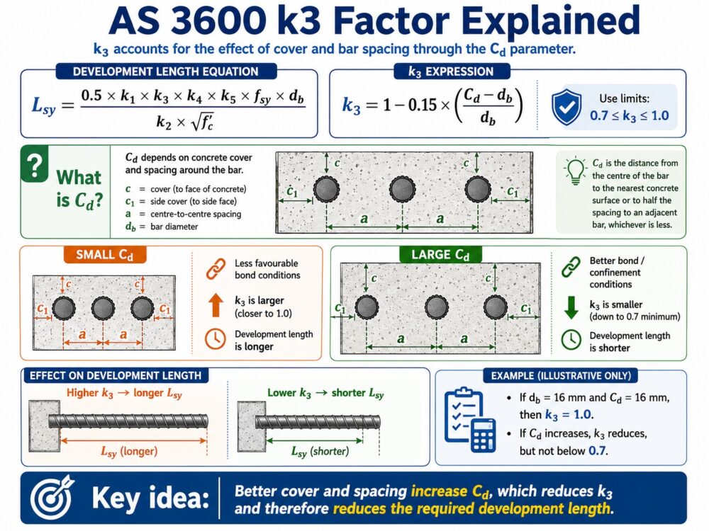
Cd is the cover/spacing parameter used in the AS 3600 development length equation. This calculator helps the user select Cd automatically based on member type and bar shape: straight, cogged/hooked, or looped.
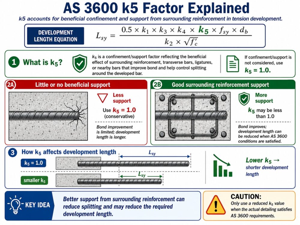
Tension Confinement Factors k4 and k5
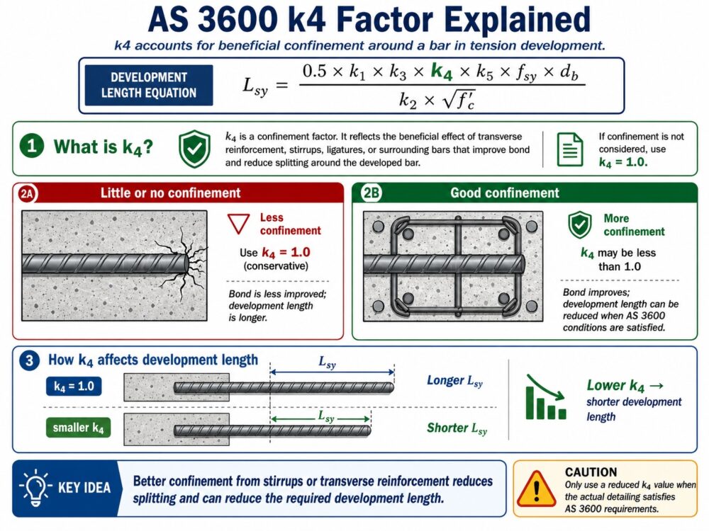
The k4 and k5 factors may reduce the tension development length when reinforcement is properly confined by stirrups, ligatures, transverse reinforcement, or other surrounding bars. In this calculator, both values are set to 1.0 by default, which gives a conservative result with no confinement reduction. Only change these values if you have checked the actual reinforcement detailing according to AS 3600.
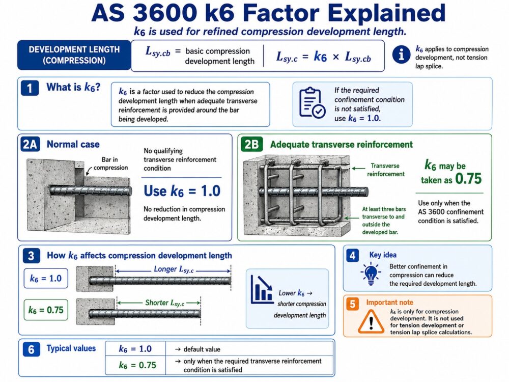
Compression Development Factor k6
The k6 factor is used for refined compression development length. It may reduce the compression development length when adequate transverse reinforcement is provided around the bar being developed. In this calculator, k6 is set to 1.0 by default. Only use a lower value, such as 0.75, if the required AS 3600 confinement condition is satisfied. The k6 factor is not used for tension lap splice calculations.
Other Splice Factors
Calculation Result
| Parameter | Value |
|---|---|
| Bar shape | — |
| Cd used | — |
| Cover c | — |
| Side cover c1 | — |
| a / 2 | — |
| Cd rule used | — |
| Basic development length | — |
| k1 | — |
| k2 | — |
| k3 | — |
| k4 | — |
| k5 | — |
| k6 | — |
| k7 / compression factor | — |
| Governing check | — |
- Automatic Cd selection for straight, cogged/hooked, and looped bars.
- Manual k4 and k5 factors for tension development.
- Manual k6 factor for compression development.
- Wide and narrow member options.
- Tension lap splice checks.
- Compression lap splice checks.
- Mesh splice option.
- Bundled bar adjustment.
AS 3600 Reinforcement Splice Length Calculator — User Manual
This online calculator is designed to help engineers, students, designers, and construction professionals estimate the required reinforcement lap splice length according to the general development and splicing concepts of AS 3600:2018 Concrete Structures. The tool provides a practical way to calculate lap splice length for different reinforcement conditions, including tension splices, compression splices, welded mesh splices, bundled bars, and different bar anchorage shapes such as straight bars, cogged or hooked bars, and looped bars.
The purpose of this calculator is to make reinforcement detailing easier to understand by guiding the user through the main input parameters used in the splice length calculation. Instead of requiring the user to manually determine every coefficient, the calculator provides explanations, diagrams, automatic Cd selection, and optional manual inputs for advanced design factors such as k4, k5, and k6.
This calculator is intended for preliminary design, educational use, comparison checks, and quick engineering estimation. Final reinforcement detailing should always be checked and approved by a qualified structural engineer using the full AS 3600 requirements and project-specific drawings. AS 3600 Section 13 covers stress development and splicing of reinforcement and tendons.
1. Selecting the Splice Type
The first step is to select the type of splice required. The calculator provides four main splice options:
Tension lap splice — wide element / slab / wall
This option is suitable for reinforcement in wider concrete elements such as slabs, walls, and other members where the reinforcement is not heavily restricted by narrow concrete dimensions.
Tension lap splice — narrow element / beam web / column
This option is used for reinforcement in narrower members such as beams, beam webs, and columns. For narrow elements, the spacing between lapped bars may affect the required lap length. The calculator includes an additional spacing check using the clear distance between lapped bars.
Compression lap splice
This option is used when reinforcement is developed or spliced in compression. Compression lap splice calculation uses a different development-length approach from tension lap splice. In this calculator, the k6 factor is included for refined compression development length.
Welded mesh lap splice in tension
This option is used for welded mesh reinforcement. If cross-bars overlap as required, the calculator applies a minimum mesh overlap. If cross-bars are not present within the splice length, the calculator treats the splice in a similar way to a tension lap splice.
2. Basic Material and Bar Inputs
The calculator requires the following basic inputs:
Bar diameter, db
This is the diameter of the reinforcing bar in millimetres. For example, an N16 bar has a diameter of 16 mm. The bar diameter affects the development length, lap splice length, Cd value, and minimum lap limits.
Steel yield strength, fsy
This is the yield strength of the reinforcement in MPa. A common value for Australian reinforcing steel is 500 MPa. A higher steel yield strength generally increases the required development and lap splice length.
Concrete compressive strength, f’c
This is the characteristic compressive strength of concrete in MPa. The calculator limits the value used in the tension development calculation to a maximum of 65 MPa, consistent with the development-length approach used in AS 3600.
3. Bar Anchorage Shape
The calculator allows the user to select the reinforcement anchorage shape. This is important because the Cd value depends on the bar shape and member type.
The available options are:
Straight bar
A straight reinforcing bar without a hook, cog, or loop.
Cogged / hooked bar
A bar with a cog or hook used to improve anchorage.
Looped bar
A bar bent into a loop shape for anchorage or detailing purposes.
The selected bar shape affects how the calculator determines the Cd parameter. For example, straight bars, hooked bars, and looped bars may use different Cd rules depending on whether the member is classified as wide or narrow.
4. Understanding Cd Selection
Cd is one of the most important parameters in the tension development length calculation. It is related to the available cover and spacing around the reinforcing bar. Many users may not know how to select Cd manually, so the calculator includes an automatic Cd selection system.
The user can choose either:
Auto calculate Cd from cover and spacing
This is the recommended option for most users. The calculator estimates Cd based on concrete cover, clear spacing between bars, bar diameter, bar shape, and member type.
Manual input Cd
This option is intended for experienced engineers who already know the correct Cd value for their reinforcement arrangement.
In automatic mode, the calculator asks for:
Concrete cover c
This is the clear cover from the concrete face to the outside surface of the reinforcing bar.
Side cover c1
This is used for narrow members such as beams and columns. It represents the side cover condition affecting bar development.
Clear spacing between adjacent bars
This is the clear distance between parallel reinforcing bars. The calculator uses this spacing together with the bar diameter to calculate the centre-to-centre spacing, called a.
The calculator then displays:
Centre-to-centre spacing, a
This is calculated as:
a = clear spacing + bar diameter
The calculator also displays the Cd rule used, such as:
Cd = min(a/2, c)
orCd = min(a/2, c1, c)
This makes the calculator more user-friendly because the user can see how Cd has been selected rather than entering it blindly.
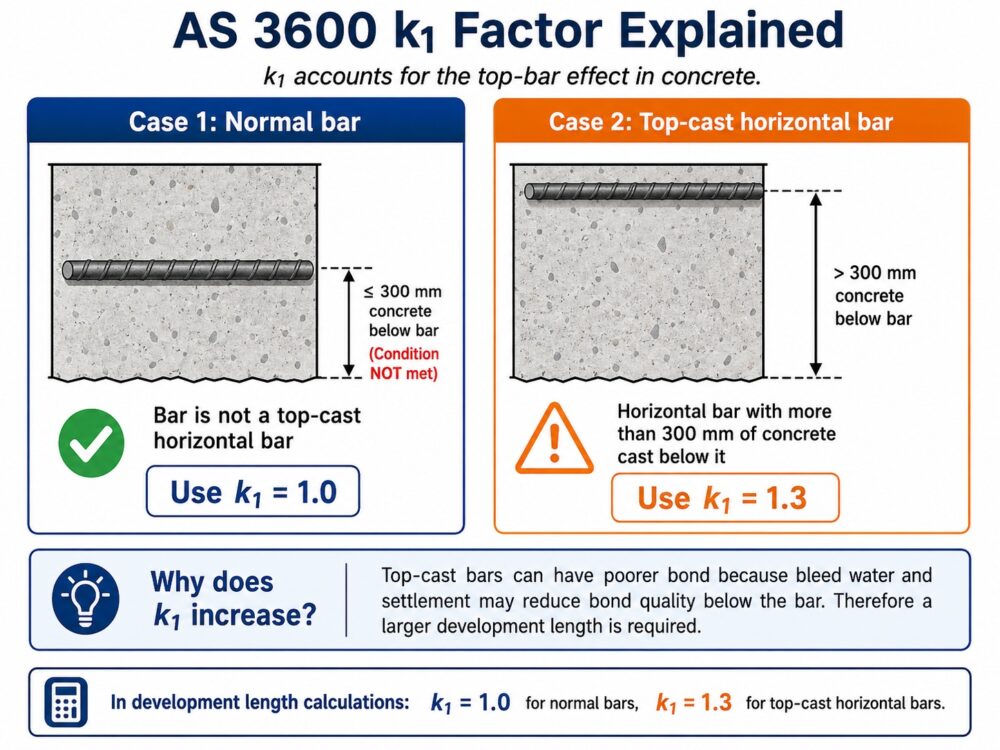
5. Top-Bar Factor k1
The calculator asks whether the bar is a horizontal bar with more than 300 mm of concrete cast below it. This condition affects the k1 factor.
If the answer is No, the calculator uses:
k1 = 1.0
If the answer is Yes, the calculator uses:
k1 = 1.3
This factor increases the development length because top-cast bars may have less favourable bond conditions.
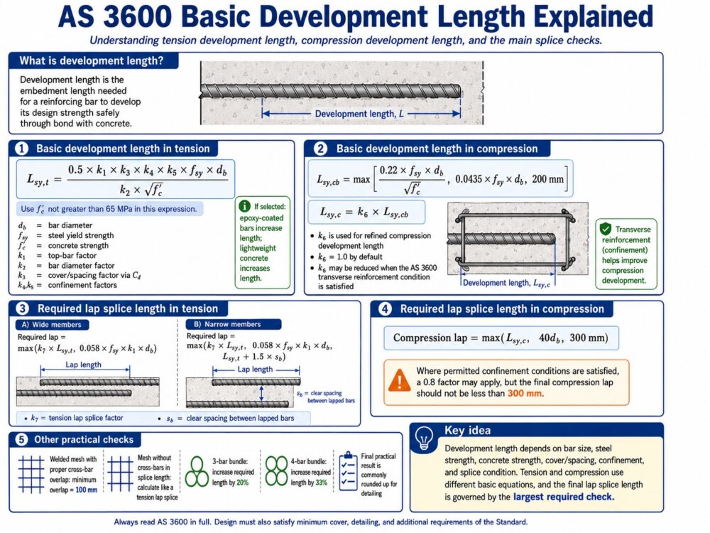
6. Tension Development Length
For tension lap splice, the calculator first calculates the tension development length. The development length depends on:
- bar diameter
- steel yield strength
- concrete strength
- k1 top-bar factor
- k2 bar diameter factor
- k3 cover and spacing factor
- k4 and k5 confinement factors
- epoxy coating condition
- lightweight concrete condition
The calculator uses the following general form:
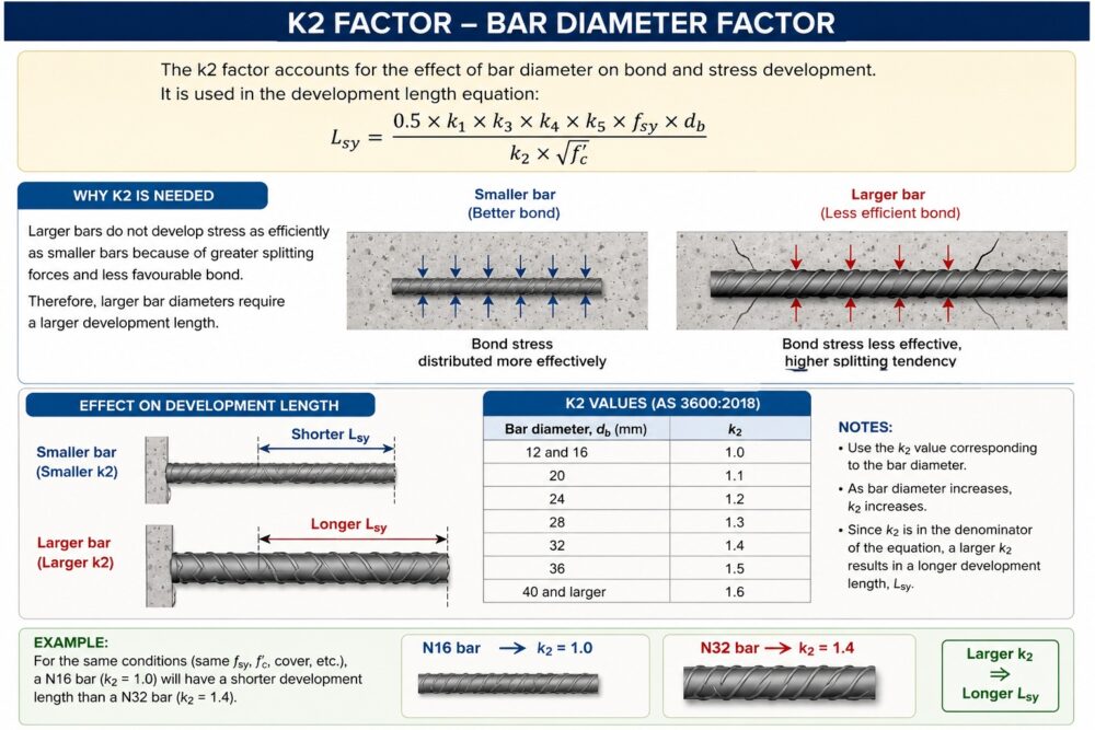
Lsy.t = (0.5 × k1 × k3 × k4 × k5 × fsy × db) / (k2 × √f'c)
The calculated development length is then modified if the user selects epoxy-coated reinforcement or lightweight concrete.
If epoxy-coated bar is selected, the calculator multiplies the development length by 1.5.
If lightweight concrete is selected, the calculator multiplies the development length by 1.3.
7. k4 and k5 Confinement Factors
The calculator includes manual inputs for k4 and k5. These factors are used for tension development and may reduce the development length when reinforcement is properly confined by transverse reinforcement, stirrups, ligatures, or other surrounding bars.
The default value for both factors is:
k4 = 1.0k5 = 1.0
This means no reduction is applied for confinement. This is generally conservative.
The user should only enter lower values for k4 and k5 if the actual reinforcement detailing has been checked against AS 3600 requirements. These factors should not be guessed. They depend on the arrangement of transverse reinforcement, spacing, confinement, bar location, and detailing conditions.
For general public use, leaving k4 and k5 as 1.0 is recommended.
8. Tension Lap Splice Calculation
After calculating the tension development length, the calculator applies the lap splice requirements.
For a wide tension member, the calculator checks:
k7 × Lsy.t
and compares it with the lower limit:
0.058 × fsy × k1 × db
The required lap splice length is taken as the larger value:
Required lap = max(k7 × Lsy.t, 0.058 × fsy × k1 × db)
For a narrow tension member, the calculator includes an additional spacing check:
Lsy.t + 1.5 × sb
where sb is the clear distance between lapped bars.
For narrow members, the required lap splice length is calculated as:
Required lap = max(k7 × Lsy.t, 0.058 × fsy × k1 × db, Lsy.t + 1.5 × sb)
If the clear distance between lapped bars is less than or equal to 3db, the calculator takes sb as zero for this additional check.
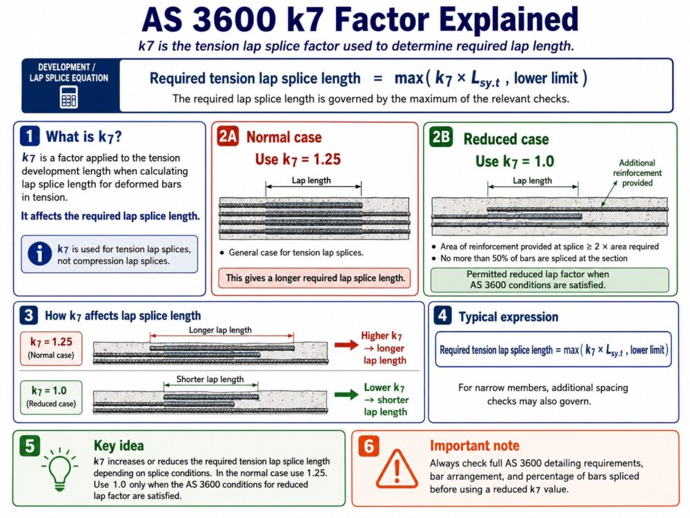
9. k7 Tension Splice Factor
The calculator provides a k7 selection for tension lap splices.
The normal case uses:
k7 = 1.25
A reduced value may be selected where the reinforcement area provided is at least twice the required area and no more than 50% of bars are spliced at the section:
k7 = 1.0
The user should only select the reduced k7 condition if it is confirmed by the actual reinforcement design and detailing.
10. Compression Lap Splice Calculation
For compression lap splice, the calculator uses a different method from tension lap splice.
First, it calculates the basic compression development length:
Lsy.cb = max((0.22 × fsy × db) / √f'c, 0.0435 × fsy × db, 200 mm)
Then the calculator applies the k6 factor:
Lsy.c = k6 × Lsy.cb
The k6 factor is used for refined compression development length. Its default value is:
k6 = 1.0
A lower value, such as 0.75, should only be used when the required transverse reinforcement condition is satisfied. The k6 factor is not used for tension lap splice calculations.
The calculator then checks the compression lap splice against minimum limits:
Compression lap = max(Lsy.c, 40db, 300 mm)
If the selected compression condition includes fitments or helical confinement, the calculator applies a 0.8 factor, while still keeping the final compression splice length not less than 300 mm.
11. Welded Mesh Lap Splice
For welded mesh, the calculator provides two options.
If cross-bars overlap as required, the calculator uses a minimum overlap of:
100 mm
If there are no cross-bars within the splice length, the calculator calculates the splice using the tension lap method.
This gives the user flexibility depending on the mesh detailing condition.
12. Bundled Bar Adjustment
The calculator includes a bundled bar adjustment factor.
The available options are:
Single bar / no bundleFactor = 1.0
3-bar bundleFactor = 1.2
4-bar bundleFactor = 1.33
After the main splice length is calculated, the calculator multiplies the result by the selected bundled bar factor.
For example:
Final lap = calculated lap × bundled bar factor
13. Final Rounding
After all checks and factors are applied, the calculator rounds the final splice length up to the nearest 10 mm.
For example:
- 463 mm becomes 470 mm
- 601 mm becomes 610 mm
- 1224 mm becomes 1230 mm
This gives a practical detailing length suitable for display and preliminary design.
14. Understanding the Result Table
The result table shows the key parameters used in the calculation.
Required lap splice length
This is the final rounded lap splice length.
Bar shape
Shows whether the selected bar is straight, cogged/hooked, looped, or mesh.
Cd used
Shows the Cd value used in the development length calculation.
Cover c and side cover c1
Shows the cover values entered by the user.
a / 2
Shows half of the centre-to-centre bar spacing.
Cd rule used
Explains which rule was used to calculate Cd.
Basic development length
Shows the calculated development length before the final lap splice checks.
k1, k2, k3, k4, k5, k6
Shows the factors used in the calculation. If a factor is not relevant to the selected splice type, the calculator displays “N/A”.
k7 / compression factor
Shows the selected splice factor or compression reduction factor.
Governing check
Explains which condition controlled the final lap splice length.
15. Important Limitations
This calculator is a design-assistance tool only. It does not replace the full AS 3600 standard, structural drawings, engineering judgement, or project-specific detailing requirements.
The calculator does not automatically verify every possible reinforcement detailing requirement, including all bar spacing, cover, anchorage, fitment, congestion, crack control, constructability, and site-specific conditions.
The user is responsible for selecting appropriate input values. In particular, k4, k5, and k6 should only be reduced from 1.0 when the relevant AS 3600 conditions are properly checked by a competent designer.
For final design, all splice lengths and reinforcement details should be reviewed and approved by a qualified structural engineer before construction.
16. Recommended Use
This calculator is useful for:
- preliminary reinforcement splice length estimation
- checking lap splice length for slabs, walls, beams, and columns
- comparing tension and compression splice conditions
- understanding the effect of cover, spacing, bar diameter, and concrete strength
- educational use for students and young engineers
- preparing approximate reinforcement detailing before final engineering review
It is not intended to replace certified structural design documentation or professional engineering judgement.
17. Simple Step-by-Step Guide
To use the calculator:
- Select the splice type.
- Enter bar diameter, steel yield strength, and concrete strength.
- Select the bar anchorage shape.
- Choose whether the bar is a top-cast horizontal bar.
- Select automatic or manual Cd input.
- Enter concrete cover, side cover if required, and clear bar spacing.
- Enter k4 and k5 if tension splice is selected. Leave them as 1.0 unless a detailed check allows reduction.
- Enter k6 if compression splice is selected. Leave it as 1.0 unless the transverse reinforcement condition is satisfied.
- Select epoxy coating, lightweight concrete, bundled bar condition, and any relevant splice condition.
- Click “Calculate Splice Length”.
- Review the final lap splice length and the governing check in the result table.
This workflow allows the user to understand not only the final splice length, but also the main factors that control the result.