
External Pressure Coefficient Cp,e
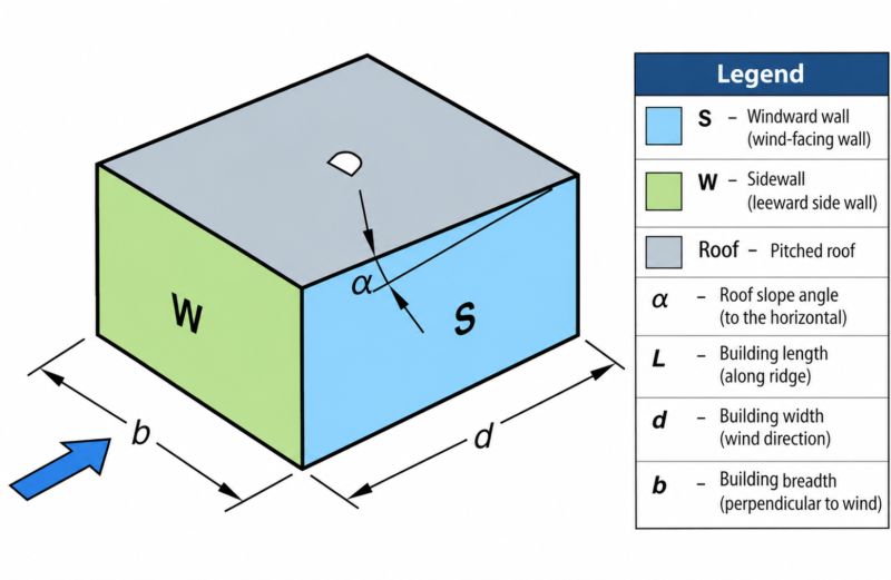
AS/NZS 1170.2:2011 • Rectangular enclosed building • Gable roof • W, S, L and D
1. Building geometry
Entered once and reused.
This simplified calculator determines Cp,e only. It does not calculate Ka, Kc,e, K, Kp, Cfig,e or wind pressure.
2. Select surface
WWindward wall
SSide wall
LLeeward wall
DDownwind roof
W — Windward wall • Table 5.2(A)
Cp,e = —
Table 5.2(A): h is read automatically from Part 1. For h > 25 m, Cp,e = +0.8 and wind speed varies with height. For a building on ground with h ≤ 25 m, the table permits +0.8 with wind speed varying with height, or +0.7 when wind speed is taken at z = h.
S — Side wall • Table 5.2(C)
Cp,e = —
| Horizontal distance from windward edge | Cp,e |
|---|---|
| 0 to 1h | −0.65 |
| 1h to 2h | −0.50 |
| 2h to 3h | −0.30 |
| > 3h | −0.20 |
Table 5.2(C): Cp,e changes with horizontal distance from the windward edge. The coloured strip shows every Table 5.2(C) zone that occurs within the entered building depth d.
L — Leeward wall • Table 5.2(B)
Cp,e = —
Table 5.2(B), gable roof, θ = 0°: for α < 10°, Cp,e depends on d/b. At α = 10°, 15° and 20°, the listed values are −0.3, −0.3 and −0.4 respectively. For α ≥ 25°, Cp,e varies from −0.75 at d/b ≤ 0.1 to −0.5 at d/b ≥ 0.3. Intermediate d/b and α values are linearly interpolated.
D — Downwind roof slope • Table 5.3(A) or 5.3(C)
For α < 10°, Table 5.3(A) gives the roof zones. For α ≥ 10°, Table 5.3(C) gives the downwind coefficient from α, h/d and, for α ≥ 25°, b/d.
Cₚ,ₑ = —
Roof coefficient distribution along d (α < 10°)
Windward edge x = 0Distance along d →x = d
| Zone | Nominal distance | Actual distance (m) | Case 1 | Case 2 | Basis |
|---|
For α ≥ 10°, check the required roof load combinations in accordance with Clause 5.4.1.