Timber Column Design Calculator
Axial Compression & Buckling Check — AS 1720.1:2010
| Step | Parameter / equation | Major axis x | Minor axis y |
|---|---|---|---|
| Press Calculate Column Capacity. | |||
1. Timber stress grade and compression strength f'c
The characteristic compression strength parallel to grain, f'c, represents the characteristic material strength used for axial compression design.
For F-graded timber the calculator automatically contains the compression strengths from AS 1720.1 Appendix H, Table H2.1.
Reference: AS 1720.1 Appendix H — Table H2.1.
2. Structural application category and capacity factor φ
The capacity factor depends on both the structural timber material and the consequence/application category.
Category 1 generally relates to appropriate house members or secondary structural members. Category 2 applies to primary structural members in structures other than houses and certain important house members. Category 3 relates to primary members in essential-service or post-disaster structures.
Reference: AS 1720.1 Clause 2.3 and Table 2.1.
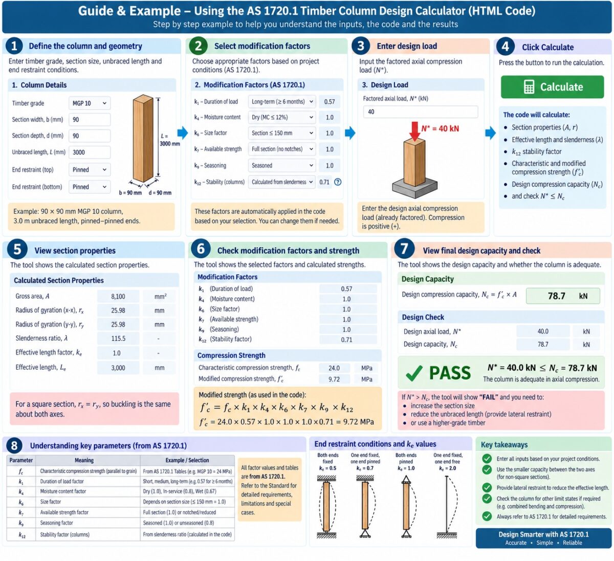
3. Load duration factor k1
Timber strength is affected by the duration of loading. Short-duration loads generally permit greater strength than long-duration actions.
5 minutes → 1.00
5 hours → 0.97
5 days → 0.94
5 months → 0.80
50+ years → 0.57
For combinations containing actions having different durations, AS 1720.1 requires the duration applicable to the shortest-duration action in the particular combination to be considered.
Reference: AS 1720.1 Clause 2.4.1.1 and Table 2.3.
4. Moisture factor k4
The factor k4 modifies timber strength to account for moisture condition.
Seasoned timber is generally assigned k4 = 1.0 when its annual average moisture content does not exceed the limit specified by AS 1720.1.
For seasoned timber with EMC exceeding 15%, this calculator uses:
Reference: AS 1720.1 Clause 2.4.2.
5. Temperature factor k6
For covered timber structures under normal ambient conditions, AS 1720.1 states that no strength modification for temperature is required; therefore:
The field remains editable so a designer can enter another value when an applicable design condition requires it.
Reference: AS 1720.1 Clause 2.4.3.
6. Effective column length factor g13
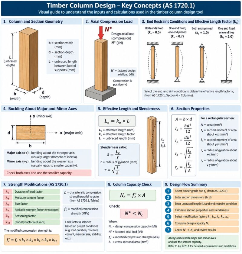
Column buckling depends strongly on the restraint at the two ends. Table 3.2 specifies the effective-length factor g13 for common restraint conditions.
A cantilever-like column therefore has a much larger effective length than a column restrained at both ends.
Reference: AS 1720.1 Table 3.2.
7. Major-axis slenderness S3
For a rectangular timber column with discrete restraints, AS 1720.1 specifies S3 as the lesser of:
S3 = g13L / d
Therefore the calculator evaluates both quantities and adopts the lower value.
Reference: AS 1720.1 Clause 3.3.2.2(a), Equations 3.3(5) and 3.3(6).
8. Minor-axis slenderness S4
Minor-axis buckling is checked separately. For discrete restraint:
S4 = g13L / b
Because the width b is often considerably smaller than depth d, minor-axis buckling frequently governs rectangular timber columns.
Reference: AS 1720.1 Clause 3.3.2.2(b), Equations 3.3(8) and 3.3(9).
9. Column material constant ρc
The material constant ρc is used with the column slenderness coefficient to determine the stability factor.
For example, the conservative Table 3.3 value for seasoned F17 is:
Reference: AS 1720.1 Table 3.3.
10. Column stability factor k12
This is the principal buckling reduction factor for a timber column. It is calculated independently for S3 and S4.
If 10 < ρcS ≤ 20: k12 = 1.5 − 0.05ρcS
If ρcS > 20: k12 = 200 / (ρcS)²
A long, slender column therefore receives a much smaller k12 than a short stocky column.
Reference: AS 1720.1 Clause 3.3.3, Equations 3.3(11a) to 3.3(11c).
11. Design compression capacity
AS 1720.1 gives the design compression capacity parallel to grain as:
Because k12 can differ between the two buckling axes, the calculator determines:
Nd,cy = capacity for buckling about minor axis y
The lower capacity governs.
Reference: AS 1720.1 Clause 3.3.1.1 and Clause 3.3.1.2.
12. Final strength check
The column passes the axial compression strength limit state when:
AND
Nd,cy ≥ N*c
The calculator also reports the utilization:
Utilization ≤ 100% indicates that the calculated axial compression capacity is not exceeded.